Table of Contents
Introduction
Moving a 50-ton transformer, steel structure, or large machine across a factory floor requires more than a simple transport vehicle. A Heavy Duty Transfer Cart uses an electric drive system to move these loads along a rail or designated route. The motor, gearbox, wheels, power supply, control system, and brake work together during each transport cycle.
In this article, we look at how the cart starts, moves, changes speed and direction, and stops, with a focus on the working principles behind each system. This helps buyers understand how a transfer cart handles heavy loads and what equipment configuration fits their working conditions.
For a detailed introduction to heavy-duty transfer carts, see the article: “What Is a Heavy Duty Transfer Cart?”
How Does a Heavy Duty Transfer Cart Work?
A Heavy Duty Transfer Cart mainly includes five parts: the power system, drive system, wheel mechanism, control system, and braking system. Each system performs a specific function during material transport.
Step 1 — Power Supply
The power supply provides electricity to the drive motor and control system. Heavy Duty Transfer Carts commonly use three power supply options.
- Battery Power: Suitable for flexible and multi-area transport.
- Low-Voltage Rail Power: Suitable for fixed routes and continuous operation.
- Cable Reel Power: Suitable for fixed routes with limited travel distance.
Power enters the electrical cabinet and is distributed to the drive system and auxiliary equipment.
Step 2 — Motor and Gearbox
The motor generates the driving force. The gearbox reduces motor speed and increases output torque.
The torque is transferred through the drive shaft to the drive wheels.
Motor → Gearbox → Drive Shaft → Drive Wheels
Motor and gearbox selection depends on load capacity, travel speed, wheel arrangement, and working frequency.
Step 3 — Wheels and Rails
For a rail transfer cart, the drive wheels run along fixed rails and generate traction. The driven wheels support the cart frame and distribute the load.
Axles, bearings, and bearing housings connect the wheel assemblies to the frame and support stable travel.
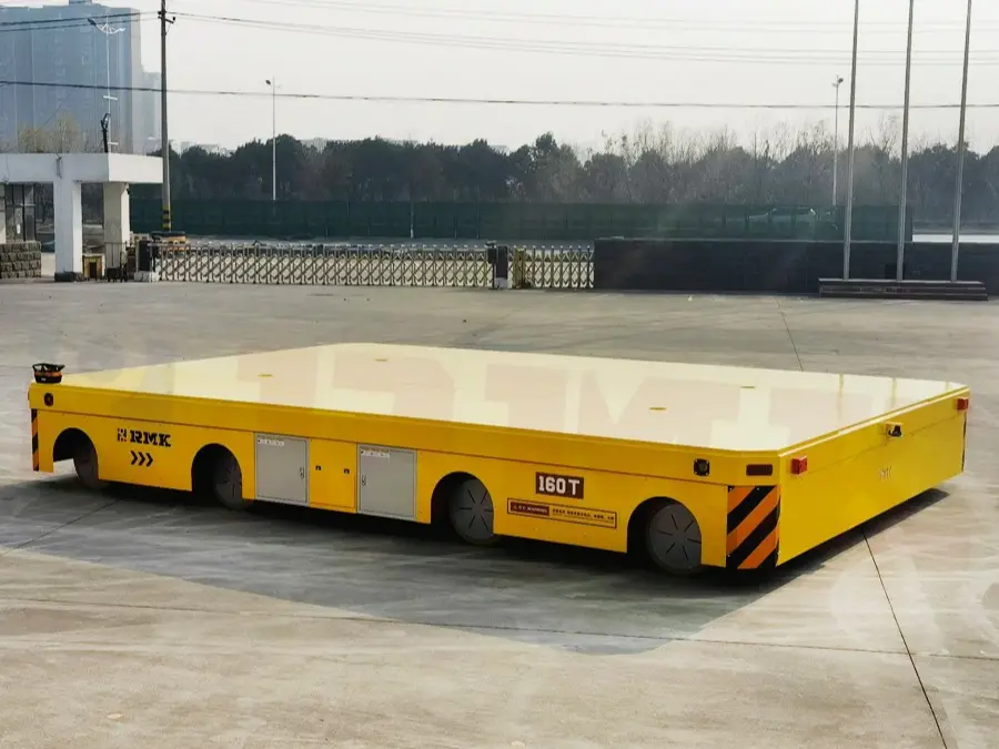
For trackless models, the wheel system runs directly on a suitable concrete or industrial floor without fixed rails.
Step 4 — Control System
The control system manages the main travel functions:
- Start and stop
- Forward and reverse
- Travel speed
- Emergency stop
- Manual or remote operation
A wireless remote or pendant can be used for manual control. A PLC and variable frequency drive can be added for automated production lines.
Step 5 — Braking System
The braking system controls deceleration and stopping. Electromagnetic brakes are commonly used with the drive system.
When the stop command is given, the motor reduces or stops its output, and the brake holds the cart in position.
Emergency braking and stopping requirements depend on the cart load, speed, route, and working environment.
Heavy Duty Transfer Cart Operating Process
A Heavy Duty Transfer Cart follows a fixed operating sequence from pre-operation inspection to loading, unloading, and return.
- 1. Pre-Operation Inspection: Check the power supply, rails, load, brakes, and safety devices before operation. Remove any obstacles from the rails and check the load against the rated capacity.
- 2. Power Supply Connection: Connect the selected power source. Check battery charge, low-voltage transformer operation, or cable reel movement as applicable.
- 3. Control Command: Use the wireless remote or pendant to select start, forward, or reverse. The PLC processes the control signal.
- 4. Motor Start and Speed Control: The motor drives the gearbox, which reduces speed and increases torque. The variable frequency drive controls travel speed from 0–25 m/min.
- 5. Rail Travel: Drive wheels generate traction on the steel rails. Driven wheels support the cart and keep it balanced as it moves to the target workstation.
- 6. Positioning and Stopping: Near the target position, the operator or positioning sensor triggers deceleration. The motor stops, and the brake holds the cart at the preset position.
- 7. Loading and Unloading: Use a forklift, lifting equipment, or hydraulic lifting platform to load or unload materials. The hydraulic platform can adjust its height for workstation connection.
- 8. Return or Standby: The cart returns to the starting point or enters the next operating cycle. For extended shutdowns, disconnect the power and apply the parking brake.
The operating process covers inspection, power connection, travel control, positioning, loading and unloading, and return or standby.
How Does a Rail Heavy Duty Transfer Cart Work?
A Rail Heavy Duty Transfer Cart runs on fixed steel rails. The rails guide the cart along a fixed route, while the drive system moves the load.
- Rail-Guided Travel: Steel wheels run on the rails and keep the cart on the track. Wheel and axle design depends on the load, platform size, and rail layout.
- Drive and Traction: The motor drives the gearbox. The gearbox increases output torque and transfers it to the drive wheels. The wheels generate traction and move the cart forward or backward.
- Control and Positioning: The control system manages start, stop, speed, and direction. Limit switches, proximity sensors, encoders, and PLC control can be used for fixed stopping points and automatic operation.
- Braking and Stopping: The braking system slows and stops the cart. Electromagnetic brakes are commonly used. Emergency stops and anti-collision devices can be added.
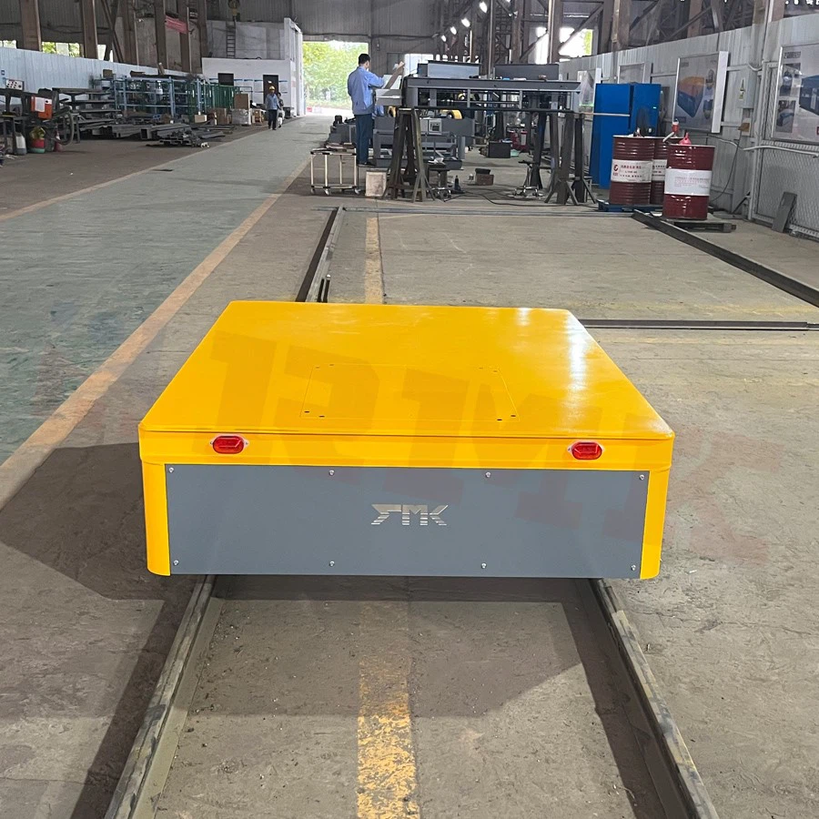
Rail Heavy Duty Transfer Carts are used for repeated heavy-load transport between fixed work areas. They move heavy loads by converting motor power into driving force through the drive system. The motor provides torque, the gearbox increases output force, and the wheels transfer the power to move the cart with the load.
Motor Torque and Gear Reduction
Heavy loads require high torque at low travel speeds. The gearbox reduces motor speed while increasing output torque, allowing the cart to start smoothly and transport heavy materials steadily.
The drive system is selected according to the load weight, travel speed, wheel size, and operating conditions.
Wheel System and Load Distribution
The wheels transfer the driving force to the rail or floor surface while supporting the total load. Multiple wheels and proper axle spacing help distribute the load evenly and reduce stress on the cart structure.
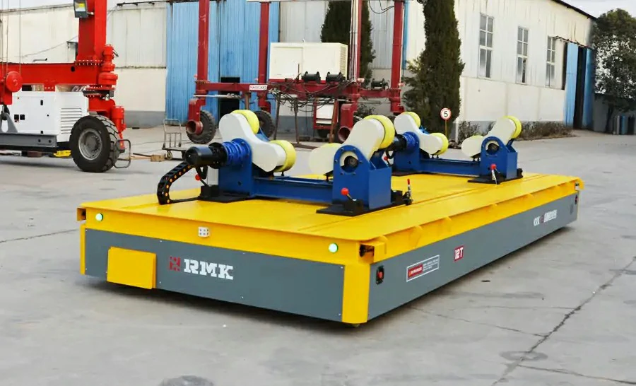
For oversized materials, the platform can be customized with different lengths, widths, and support designs.
For example, a 30-meter-long Rail-Guided Vehicle (RGV) can be designed for transporting extra-long steel pipes and similar materials.
Factors Affecting Movement Performance
| Factor | Impact on Movement |
|---|---|
| Load Capacity | Determines required motor torque and drive strength |
| Travel Speed | Affects motor and gearbox selection |
| Wheel Design | Influences traction and load support |
| Operating Conditions | Affects wheel wear and drive performance |
How Does a Heavy Duty Transfer Cart Control Speed and Direction?
The speed and travel direction of a Heavy Duty Transfer Cart are controlled by the electrical control system, which regulates motor operation during movement.
- Speed Control: A variable frequency drive (VFD) adjusts the motor speed during starting, running, and stopping. Smooth acceleration and deceleration help reduce impact on the cart structure, wheels, and transported load.
- Forward and Reverse: The control system changes the motor rotation direction to move the cart forward or backward. Operators can select the travel direction through a pendant controller or wireless remote.
Heavy Duty Transfer Carts are available with manual, remote, or automatic control options. For automated operation, PLC control and sensors can be added to manage travel commands and movement processes.
How Does the Power Supply Affect Transfer Cart Operation?
Different power supplies suit different operating conditions.
| Power Supply | Application |
|---|---|
| Battery | Flexible routes and multi-area transport |
| Low-Voltage Rail | Fixed routes and frequent operation |
| Cable Reel | Fixed routes and short-to-medium travel distances |
Battery capacity, cable length, rail layout, and operating frequency should be considered when selecting the power system.
How Does a Heavy Duty Transfer Cart Stop?
A Heavy Duty Transfer Cart uses the braking and control systems to stop the vehicle.
Normal Braking: The control system reduces the motor speed and activates the brake when the cart reaches the stopping point.
Emergency Stop: An emergency stop button immediately cuts the drive command. The braking system then stops and holds the cart.
Anti-Collision Protection: Sensors, buffers, warning lights, and alarms can be added to reduce collision risks.
The safety configuration depends on the operating environment, travel route, and automation level.
What Are the Parts That Make a Transfer Cart Work?
A Heavy Duty Transfer Cart consists of several systems that work together to move and control heavy loads.
| Component | Main Function |
|---|---|
| Frame | Welded steel structure that supports the load and holds the main components. |
| Motor | Provides driving power for the cart. AC or DC motors can be used according to the cart design. |
| Speed Reducer | Reduces motor speed and increases output torque for heavy-load travel. |
| Power Supply | Provides electricity through batteries, cable reels, low-voltage rails, or other suitable systems. |
| Control System | Controls starting, stopping, direction, speed, and other travel functions through the control cabinet, PLC, or inverter. |
| Wheels | Support the cart and transfer driving force to the ground or rails. Rail carts use steel rail wheels, while trackless carts use wheels with steering systems. |
| Braking System | Controls deceleration and stops the cart. Electromagnetic or mechanical brakes can be used. |
| Safety Devices | Include emergency stops, warning lights, alarms, buffers, limit switches, and anti-collision devices. |
The component configuration is selected according to load capacity, travel route, power supply, operating frequency, and automation requirements.
For details on the classification and applications of transfer cart wheels, see the article: “Types of Wheels for Transfer Carts”
Maintenance and usage precautions for the power supply are critical for transfer carts, as they affect the equipment’s operational efficiency and costs. For details, see:
- Battery Management for the Battery Transfer Cart
- How to Solve the Problem of Transfer Trolley Batteries Not Lasting as Long in Winter?
Proper safety configurations and regular maintenance schedules for transfer carts not only ensure more efficient material handling operations but also extend the equipment’s service life. For more information, read: Battery-Powered Transfer Cart Maintenance Guide: Daily Inspection and Battery Care
What Affects Heavy Duty Transfer Cart Performance?
Several factors affect how a Heavy Duty Transfer Cart runs and handles loads.
| Factor | Main Effect |
|---|---|
| Load Capacity | Determines frame, motor, wheels, and braking requirements. |
| Travel Distance | Affects power supply and battery capacity. |
| Travel Speed | Affects motor and gearbox selection. |
| Route | Determines rail or trackless configuration. |
| Operating Frequency | Affects drive and cooling requirements. |
| Working Environment | Affects motor, electrical, and safety configurations. |
| Automation Level | Determines PLC, sensors, positioning, and control systems. |
The cart configuration should match the load, route, operating conditions, and control requirements.
How to Choose a Heavy Duty Transfer Cart?
Choose the transfer cart according to the load, route, distance, working frequency, power supply, and site conditions.
- 1. Load Capacity — Check the maximum load weight and load dimensions.
- 2. Platform Size — Select the platform length and width according to the load size and support points.
- 3. Travel Route — Choose a rail or trackless cart based on the transport route and floor conditions.
- 4. Travel Distance — Check the distance between loading and unloading points.
- 5. Travel Speed — Select the running speed according to the transport cycle and site requirements.
- 6. Power Supply — Choose battery power, low-voltage rail power, or cable reel power according to the route and operating conditions.
- 7. Working Frequency — Consider the number of transport cycles and daily operating hours.
- 8. Working Environment — Check site conditions such as temperature, dust, water, and heat.
- 9. Control Method — Choose pendant control, wireless remote control, PLC control, or automatic control based on the operating method.
- 10. Safety Requirements — Specify brakes, emergency stops, alarms, buffers, and anti-collision devices according to the site.
For a custom Heavy Duty Transfer Cart, provide the load weight, load dimensions, travel distance, route, operating frequency, power supply, and working environment to the manufacturer.
Different types of heavy-duty transfer carts are suited for different work scenarios. Which type is right for your factory? Check out this article to learn how to choose the right transfer cart for your needs: Heavy Duty Transfer Cart Buying Guide: How to Choose the Right Model
Conclusion
A Heavy Duty Transfer Cart uses the power supply, motor, gearbox, wheels, control system, and braking system to move heavy loads along a fixed or designated route. Load capacity, platform size, travel distance, power supply, route, and working conditions determine the cart configuration.
REMARKABLE provides Heavy Duty Transfer Carts for different load capacities and operating conditions, with customized platforms, drive systems, power supplies, and control systems. Contact us with your load, route, and operating requirements for a suitable transfer cart solution.
Email: transfercart@rmkzn.com
Phone: +86-18637369355
FAQ
How does a Heavy Duty Transfer Cart work?
A Heavy Duty Transfer Cart uses an electric drive system to move heavy loads along rails or a designated route. The motor, gearbox, wheels, control system, and braking system work together during operation.
How does a transfer cart get power?
A transfer cart can use batteries, low-voltage rail power, or a cable reel. The power supply is selected according to the travel route, distance, and operating conditions.
How does a rail transfer cart move?
The motor drives the gearbox and drive wheels. Steel wheels run along fixed rails and move the cart along the designated route.
How does a transfer cart carry heavy loads?
The steel frame supports the load and distributes its weight across the wheel assemblies. Motor torque and gear reduction provide the force needed to move the loaded cart.
How is the speed of a Heavy Duty Transfer Cart controlled?
A variable frequency drive controls motor speed during travel. The control system can also manage acceleration, deceleration, and stopping.
How does a transfer cart stop?
The control system reduces or stops motor output, while the braking system stops and holds the cart. Emergency stop devices can be used when required.
Can a Heavy Duty Transfer Cart operate automatically?
Yes. PLC control, positioning sensors, limit switches, and other control devices can be integrated for automatic transport and positioning.
What factors affect transfer cart performance?
Load capacity, travel speed, route, travel distance, power supply, working frequency, floor or rail conditions, and working environment all affect transfer cart performance.